
A More Rigorous Approach to Assessing Catastrophe Risk for Industrial Facilities
May 14, 2010
 Editor’s Note: Last year, the release of the AIR Earthquake Model for the U.S. featured a radically new, component-based approach to modeling the vulnerability of complex industrial facilities. This year, those capabilities have been extended to hurricane risk. The upcoming Version 12.0 release of the AIR U.S. Hurricane Model will feature the capability to assess potential property and business interruption losses to industrial facilities from wind or storm surge. In this article, AIR Principal Engineer and Director of Engineering Analysis and Research Dr. Paolo Bazzurro describes how AIR has approached the challenging task of modeling the vulnerability of facilities that may be comprised of dozens if not hundreds of widely different and often interconnected components.
By Paolo Bazzurro
The article: Gives an overview of the AIR’s approach to modeling catastrophe risk to complex industrial facilities. Highlights: The component-based approach treats an industrial facility not as a single entity but as the sum of all its constituent components, including the interconnections between its sub-units and their reliance on lifelines. It is an approach that represents a quantum leap over other models’ traditional reliance on expert opinion. And AIR’s implementation provides users with the flexibility to obtain more refined loss estimates when information on the composition of a specific facility is available. |
Industrial Facilities: Inherent Complexity
Natural catastrophes cause significant property and business interruption losses to industrial facilities throughout the world. Ten years ago the Tupras oil refineries in Turkey were damaged by the M7.4 Izmit Earthquake, in 2007 the Kashiwazaki nuclear power plant in Japan was damaged by the M6.6 Niigata Chuetsu‐Oki Earthquake, and in 2008 numerous petrochemical facilities in the United States were damaged by Hurricane Ike.
Evaluating catastrophe risk to industrial facilities is a complex task. Consider (while acknowledging the over-simplification) that commercial structures consist, by and large, of a series of columns and beams with walls in between and a roof on top. In contrast, industrial facilities comprise a large number and a wide variety of assets, which may include tanks, flares, cooling towers, transmission systems and transportation assets, in addition to structures and contents both like and unlike more standard commercial structures and contents. Making matters even more complex is the high degree of interconnectivity between these disparate and facility-specific elements—through electrical transmission lines, transportation links, product chains, and lifelines (dependence, for example, on the continuity of public utilities, supply chains, transportation networks and the like) and the actions of civil authorities).
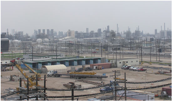
Deconstructing Industrial Facilities: A Bottom-Up Approach
To estimate potential losses to industrial facilities caused by hurricanes and earthquakes, AIR employs a component-based approach to the development of damage functions (mathematical relationships that translate the intensity of the hazard affecting a facility into monetary losses). A radical departure from traditional approaches, such as those used by HAZUS1 and ATC-132 in which industrial facilities are treated as a single entity, AIR’s approach assesses the overall damageability of various kinds of industrial facilities based on the damageability of the individual assets—the components and sub-components—that comprise the facility.
These assets can be divided into three broad categories: “Buildings and Structures,” “Machinery and Equipment,” and “Stock and Supplies.” Each of these categories can be further broken down into classes and sub-classes of components whose presence and relative numbers are largely determined by a facility’s purpose: heavy industrial or light industrial production, manufacturing, petrochemical production, power generation, or something else.
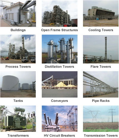
“Buildings and Structures” include both buildings—offices, warehouses, control facilities, etc.—and non-building structures, such as open-frame supporting scaffolding, loading docks and pipe racks. Also included are specialized structures such as chimneys, flares, process towers, cooling towers, and transmission systems. The “Machinery and Equipment” category includes mechanical and electrical equipment, tanks, silos, piping networks, free-standing equipment, and equipment housed in open-frame structures.
In addition to the materials that make up the “Stock and Supplies” category are the attributes of those materials: for example, how they will react to damage to (or failure of) their storage containers, their flammability, toxicity, whether or not they are anchored, and so on. This category can account for a significant portion of the replacement value of an entire facility.
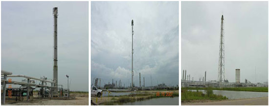
The ruling principle in developing the categories was to group components according to their similarities in structural characteristics and functionality. The sub-classes reflect significant differences in vulnerability that may exist within a component class. For example, flare towers are a component in the “Buildings and Structures” category, but flare towers may be freestanding, guyed, or derrick-supported. Each will behave differently when subjected to hurricane force winds—and indeed each will behave differently at different wind speeds. Similarly, tanks may be anchored or not; clearly, the presence of foundation anchorage will affect a tank’s vulnerability to storm surge or ground shaking. Because each sub-class exhibits a different characteristic response to environmental loads, a damage function has been developed for each.
Examples of industrial components are shown in Figure 2. The sub-classes of flare towers are illustrated in Figure 3.
Developing Component-Level Damage Functions
The traditional approach to estimating the vulnerability of industrial facilities was to treat them as a single entity or, at best, as a collection of industrial buildings, while the components—the equipment, flare towers, process towers, etc.—were treated either as building-like structures or simply as building contents. The relationship between hazard intensity and damage ratio was obtained using an opaque method based mostly on expert opinion, which can be highly arbitrary and therefore intrinsically questionable.
In the AIR U.S. hurricane and earthquake models, damage functions have been developed at the component level. Indeed, more than 400 damage functions were developed for roughly 550 distinct components and sub-components. Their development was based on findings from detailed, site-specific, engineering-based risk assessments conducted by AIR through AIR’s Catastrophe Risk Engineering (CRE) services—assessments that encompass engineering studies, structural calculations, materials tests and post-disaster field surveys. By developing component-level damage functions based on engineering analysis and hard data, AIR has removed as much as possible reliance on expert opinion and has replaced it with a defensible, transparent and reproducible methodology and damage functions that are realistic and robust.
Developing Damage Functions for Storage TanksStorage tanks are probably the most common components found in industrial facilities. Not all tanks are the same, however. They can have different aspect ratios (the ratio of height to diameter), different levels to which they are filled, different methods to anchor them, and so on, all of which affect their vulnerability. Large-diameter storage tanks (which have a relatively low aspect ratio), for example, tend to buckle at lower wind speeds than tanks with higher aspect ratios. Tanks with very high aspect ratios, however, also can fail—by being overturned or caused to slide before their walls ever begin to buckle; however, such tanks are typically anchored at the foundation. 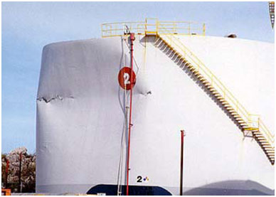 Figure 4. Tank damage caused by hurricane winds (Source: AIR) AIR engineers undertook a variety of engineering studies in developing damage functions for storage tanks. In one set of tests, structural analytical models of storage tanks were developed using computer engineering software. Wind pressure distributions (based on the published results of wind tunnel studies) were applied to the models incrementally, thus simulating increasing wind loads (Figure 5a). The loading-factor was raised until elastic buckling developed, indicating a local failure of the tank wall (Figure 5b). These tests were repeated with the storage tanks modeled to hold three different levels of liquid (empty, half-full, and full).  Figure 5. (a) Distribution of wind pressure around a tank wall and (b) Deflection of tank wall at onset of elastic buckling (colored bands represent different levels of tank shell thickness) |
Developing Robust Loss Estimates for the Facility
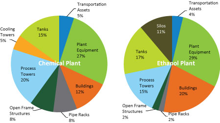
Clearly, different kinds of facilities will have different kinds of components; or they may have similar components but in different proportions (see Figure 6). Given the wide variability in the vulnerability of different industrial components, the specific distribution of component classes within various kinds of facilities needs to be taken into account when the vulnerability of an entire plant is determined.
Insurance policies, however, are not written for individual tanks or flare towers or pipe racks. Therefore, ultimately, the task of a model is to estimate potential losses to an entire industrial facility. To do this—that is, to produce a damage function for a facility as a whole—AIR combines, or aggregates, the component/sub-component damage functions using weights that represents that component’s share of the replacement value of the entire facility.
Figure 6 below shows the different shares (or percentages) of total replacement value attributed to the components of two different industrial facilities. Although the individual components of the two plants are nearly the same, their constituent proportions (as a percent of total replacement value) are quite different.
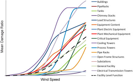
As noted earlier, specific components and their representation will vary from one facility to another. The distributions of components and sub-components by facility type represented in the AIR damage functions for industrial facilities were based on extensive knowledge gained through AIR’s site-specific risk assessments. However, they represent the average, or typical, facility of a given type. Recognizing that each facility is unique, AIR’s CLASIC/2 software allows users who have access to facility-specific information to specify the various actual constituent components and sub-components present, their characteristics (anchorage, aspect ratios for tanks, etc.), and their percentage of the site replacement value. This ability to specify the composition of each facility, when known, will result in better loss estimates.
When the composition of the facility is not known to the underwriter or portfolio manager, the AIR model includes a “General” (or “unknown”) damage function that can approximate losses for facilities for which little or no specific information is available, including facility type. The damage function for this “General” industrial facility is a weighted average of the damage functions for all the known facility types. However, because the composition of various industrial facilities can vary widely, loss estimates generated for a specific plant by specifying its actual composition can differ considerably from those of the weighted average for all facility types.
Business Interruption Losses for Industrial Facilities
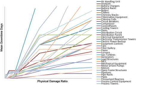
Losses caused by the interruption of operations often can be greater than the losses caused by physical damage to a plant. To estimate business interruption for an entire industrial facility, time element “damage” functions are first determined for each component—functions that relate damage (sustained by both physical components that are part of the different product chains and by lifelines) to downtime. Downtime is estimated for every stage of the damage assessment and repair process for each damaged component.
The high degree of site-specific connectivity and the complexity of the product chains that exist at most plants make the estimation of downtime for industrial facilities a challenge. It is a many-faceted calculation involving numerous operations, including evaluations of onsite process interactions, bottlenecks and redundancies, offsite interdependencies, and generators of revenue. It is accomplished by building a “network model” that constructs a simulation of the many interconnections between components, processes, lifelines, and product chains and accounts for components to be idle even if undamaged or already fixed in the event that other components or lifelines remain down. Figure 6 below displays the downtime (or time element) functions for selected industrial facility components developed through these sets of operations.
Conclusion
AIR’s site-specific studies have provided a detailed understanding of the distribution of industrial components by plant type, and of the differences in their physical characteristics and replacement values. Industrial plants often have similar components but in radically different proportions, so an accurate distribution of component classes within different plant types is essential for deriving the vulnerability of an entire plant. And by considering the interconnectivity between components in a variety of product chains, AIR’s enhanced component-based methodology has also been extended to the assessment of BI losses.
The bottom-up, component-based approach to assessing catastrophe risk to industrial facilities generates loss estimates that are realistic, transparent and defensible. And it represents a quantum leap in terms of sophistication and robustness over traditional approaches based on expert opinion.
1 A GIS-based natural-hazard loss-estimation software package developed by the U.S. Federal Emergency Management Agency (FEMA).
2 Applied Technology Council 1985, “Earthquake Damage Evaluation Data for California,” Report 13, funded by Federal Emergency Management Agency.
